Biasing is the term given to the adjustment of the output devices.
Many people believe that only valve amps are biased, this is a bit of a myth. To understand biasing we need to understand that to make a full wave we need drivers for the plus part of the wave and the negative. This can be the pair of valves you see in the back of your amp, that is why valve amps generally have pairs or quads as their output valves, there are other configurations however this is the most common layout and is known as a Class AB. The purpose of the driver be a transistor or valve, is to convert the low current of the signal into a high current designed to drive speakers.
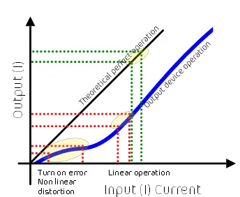
Due to the losses and construction of a silicon transistor/ MOSFET means that it does not start to operate until it has a minimum of about 0.6V to turn it on. As you can imagine that levels below this do not get amplified correctly and gives the wave a ‘knee’ curve and non-linear operation as can be seen on the below graph.

Biasing is the art of starting a output device conducting current in it’s ‘idle’ state so the device is already turned on and gives a better linear response.
Ok great, so I can just turn the bias up and it doesn’t really matter? NO!
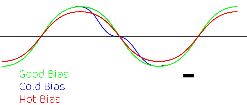
When I mentioned above the idea of biasing is to have the transistor or valve conducting electricity in idle to remove the turn on knee error this means that the output devices are conducting slight current. In a push pull arrangement this means that a small amount of current on the + added to a small amount of current on the – should equal and give 0 to avoid any DC appearing on the speaker. If the balance is off you could have DC voltage on the speaker on either + or – V and this will damage the speaker. Taking this small amount of current flowing continuously when the amp isn’t doing anything creates heat and is using the output devices which means they’re working all the time. If the bias is set too high they’ll be working too hard when not needed and can result in reduced output as there will be a wasted power element used on the balancing, not enough and the turn on non linear amplification will appear. Now you can probably guess there is a section in the middle that is efficient to the amplifier, and also sounds the most accurate based on a pure wave.
Measuring biasing varies from Valve to transistor. However is essentially measuring the quicient current draw and DC offset balance for transistors, and measuring the cathodic current draw and supply voltage on a valve. Using ohms law you can work out the power P=V2/ R where the resistor is a dummy shunt put inline with the supply of the valve. Referencing to the valve model and datasheet will give you the recommended power window of operation.
However typically a rule of thumb is 15W for EL34/ KT88/ 5881, 18W for 6L6, and 7.2W for EL84 6V6.
Typical image of how biasing affects a sine wave.

